Aspheric lens
An aspheric lens or asphere is a lens whose surface profiles are not portions of a sphere or cylinder. In photography, a lens assembly that includes an aspheric element is often called an aspherical lens.
The asphere's more complex surface profile can reduce or eliminate spherical aberration and also reduce other optical aberrations compared to a simple lens. A single aspheric lens can often replace a much more complex multi-lens system. The resulting device is smaller and lighter, and possibly cheaper than the multi-lens design. Aspheric elements are used in the design of multi-element wide-angle and fast normal lenses to reduce aberrations. They are also used in combination with reflective elements (catadioptric systems) such as the aspherical Schmidt corrector plate used in the Schmidt cameras and the Schmidt-Cassegrain telescopes.
Aspheric lenses are also sometimes used for eyeglasses. These are typically designed to give a thinner lens, and also distort the viewer's eyes less as seen by other people, producing better aesthetic appearance.[1] Aspheric eyeglass lenses typically do not provide better vision than standard "best form" lenses, but rather allow a thinner, flatter lens to be made without compromising the optical performance.[1]
Contents |
Surface profile
While in principle aspheric surfaces can take a wide variety of forms, aspheric lenses are often designed with surfaces of the form
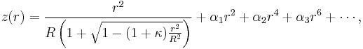
where the optic axis is presumed to lie in the z direction, and  is the sag—the z-component of the displacement of the surface from the vertex, at distance
  from the axis. The coefficients
  describe the deviation of the surface from the axially symmetric quadric surface specified by
  and
and  .
.
If the coefficients are all zero, then is the radius of curvature and is the conic constant, as measured at the vertex (where  ). In this case, the surface has the form of a conic section rotated about the optic axis, with form determined by :
-
Conic section 
hyperbola 
parabola 
ellipse (surface is a prolate spheroid) 
sphere 
ellipse (surface is an oblate spheroid)
Manufacture
Small glass or plastic aspheric lenses can be made by molding, which allows cheap mass production. Due to their low cost and good performance, molded aspheres are commonly used in inexpensive consumer cameras, camera phones, and CD players. They are also commonly used for laser diode collimation, and for coupling light into and out of optical fibers.
Larger aspheres are made by grinding and polishing. Lenses produced by these techniques are used in telescopes, projection TVs, missile guidance systems, and scientific research instruments. They can be made by point-contact contouring to roughly the right form[3] which is then polished to its final shape. In other designs, such as the Schmidt systems, the aspheric corrector plate can be made by using a vacuum to distort an optically parallel plate into a curve which is then polished "flat" on one side. Aspheric surfaces can also be made by polishing with a small tool with a compliant surface that conforms to the optic, although precise control of the surface form and quality is difficult, and the results may change as the tool wears.
Single-point diamond turning is an alternate process, in which a computer-controlled lathe uses a diamond tip to directly cut the desired profile into a piece of glass or another optical material. Diamond turning is slow and has limitations in the materials on which it can be used, and the surface accuracy and smoothness that can be achieved.[3] It is particularly useful for infrared optics.
Several "finishing" methods can be used to improve the precision and surface quality of the polished surface. These include ion-beam finishing, abrasive water jets, and magnetorheological finishing, in which a magnetically guided fluid jet is used to remove material from the surface.[3]
Another method for producing aspheric lenses is by depositing optical resin onto a spherical lens to form a composite lens of aspherical shape. Plasma ablation has also been proposed.
The non-spherical curvature of an aspheric lens can also be created by blending from a spherical into an aspherical curvature by grinding the curvatures off-axis. Dual rotating axis grinding can be used for high index glass that isn't easily spin molded, as the CR-39 resin lens is. Techniques such as laser ablation can also be used to modify the curvature of a lens, but the polish quality of the resulting surfaces is not as good as those achieved with lapidary techniques.
Standards for the dispensing of prescription eyeglass lenses discourage the use of curvatures that deviate from definite focal lengths. Multiple focal lengths are accepted in the form of bifocals, trifocals, vari-focals, and cylindrical components for astigmatism.
Ophthalmic uses
Like other lenses for vision correction, aspheric lenses can be categorized as convex or concave.
Convex aspheric curvatures are used in many presbyopic vari-focal lenses to increase the optical power over part of the lens, aiding in near-pointed tasks such as reading. The reading portion is an aspheric "progressive add". Also, in aphakia or extreme hyperopia, high plus power aspheric lenses can be prescribed, but this practice is becoming obsolete, replaced by surgical implants of intra-ocular lenses. Many convex types of lens have been approved by governing agencies regulating prescriptions.
Concave aspheres are used for the correction of high myopia. They are not commercially available from optical dispensaries, but rather must be specially ordered with instructions from the fitting practitioner, much like how a prosthetic is customized for an individual.
The range of lens powers available to dispensing opticians for filling prescriptions, even in an aspheric form, is limited practically by the size of the image formed on the retina. High minus lenses cause an image so small that shape and form aren't discernible, generally at about -15 diopters, while high plus lenses cause a tunnel of imagery so large that objects appear to pop in and out of a reduced field of view, generally at about +15 diopters.
In prescriptions for both farsightedness and nearsightedness, the lens curve flattens toward the edge of the glass,[4] except for progressive reading adds for presbyopia, where seamless vari-focal portions change toward a progressively more plus diopter. High minus aspheres for myopes do not necessarily need progressive add portions, because the design of the lens curvature already progresses toward a less-minus/more-plus dioptric power from the center of the lens to the edge. High plus aspheres for hyperopes progress toward less-plus at the periphery. The aspheric curvature on high plus lenses are ground on the anterior side of the lens, whereas the aspheric curvature of high minus lenses are ground onto the posterior side of the lens. Progressive add reading portions for plus lenses are also ground onto the anterior surface of the lens. The blended curvature of aspheres reduces scotoma, a ringed blind spot.
Non-optical advantages
High minus lenses, especially finished in a plastic resin lens, have dangerously curved edges that do not bevel off sufficiently to protect the eye from injury. Serious injury to the eye is often seen from blunt trauma, when the edge of a thick lens has been mounted in a poorly fitted frame. Bi-concave lens design is different from the usual "best form" curvatures ordered in low power thin lens prescriptions, but by splitting the curvature in thirds or so, a thinner high minus lens is developed, although costing more, and more difficult to dispense.
History
In 984, Ibn Sahl first discovered the law of refraction, usually called Snell's law,[5][6] which he used to work out the shapes of anaclastic lenses that focus light with no geometric aberrations.
Early attempts at making aspheric lenses to correct spherical aberration were made by René Descartes in the 1620s, and by Constantijn Huygens in the 1630s; the cross-section of the shape devised by Descartes for this purpose is known as a Cartesian oval. The Visby lenses produced by Vikings on the island of Gotland in the 10th or 11th century are also aspheric, but there is no evidence that the science behind the technique was known, they were 'simply' produced by craftsmen working from experience of what worked.
Francis Smethwick ground the first high-quality aspheric lenses and presented them to the Royal Society on February 27, 1667/8.[7] A telescope containing three aspheric elements was judged superior to a "common, yet very good" telescope used for comparison, and aspheric reading and burning glasses also outdid their spherical equivalents.
Moritz von Rohr is usually credited with the design of the first aspheric lenses for eyeglasses. He invented the eyeglass lens designs that became the Zeiss Punktal lenses.
The world's first commercial, mass produced aspheric lens element was manufactured by Elgeet for use in the Golden Navitar 12mm f1.2 wide angle lens for use on 16mm movie cameras in 1956. This lens received a great deal of industry acclaim during its day. The aspheric elements were created by the use of a membrane polishing technique.
Testing of aspheric lens systems
The optical quality of a lens system can be tested in an optics or physics laboratory using bench apertures, optic tubes, lenses, and a source. Refractive and reflective optical properties can be tabulated as a function of wavelength, to approximate system performances; tolerances and errors can also be evaluated. In addition to focal integrity, aspheric lens systems can be tested for aberrations before being deployed.
See also
References
- ^ a b Meister, Darryl. "Ophthalmic Lens Design". OptiCampus.com. http://www.opticampus.com/cecourse.php?url=lens_design/&OPTICAMP=f1e4252df70c63961503c46d0c8d8b60#asphericity.
- ^ Pruss, Christof; et al. (April 2008). "Testing aspheres". Optics & Photonics News 19 (4): 26. Bibcode 2008OptPN..19...26H. doi:10.1364/OPN.19.4.000026.
- ^ a b c Shorey, Aric B.; Golini, Don; Kordonski, William (October 2007). "Surface finishing of complex optics". Optics and Photonics News (Optical Society of America) 18 (10): 14–16.
- ^ Jalie, Mo (2003). Ophthalmic Lenses and Dispensing. Elsevier Health Sciences. p. 178. ISBN 0750655267. http://books.google.com/?id=Zl45vQkISCwC&pg=PA173&dq=dispensing+for+aphakia#PPA178,M1.
- ^ K. B. Wolf, "Geometry and dynamics in refracting systems", European Journal of Physics 16, p. 14–20, 1995.
- ^ R. Rashed, "A pioneer in anaclastics: Ibn Sahl on burning mirrors and lenses", Isis 81, p. 464–491, 1990.
- ^ "An Account of the Invention of Grinding Optick and Burning-Glasses, of a Figure not-Spherical, produced before the Royal Society" (PDF). Philosophical Transactions of the Royal Society 3 (33–44): 631–2. 1668 (NS). doi:10.1098/rstl.1668.0005. http://www.journals.royalsoc.ac.uk/link.asp?id=k4572442582r1255. Retrieved Nov. 8, 2008.